# Electric Diamond Knife Gate Valve in Aeration Systems: Principles, Selection and Commissioning of Electric Linear Control Valves
In wastewater treatment, biological fermentation, industrial air supply and certain powder-conveying systems, pipelines need more than simple on-off control — the flow must be continuously adjusted to match process load. Conventional knife gate valves are better suited to fully-open or fully-closed duty. Running them at small openings over long periods tends to cause erratic flow changes, disc vibration, localized erosion and poor control stability.
The electric diamond knife gate valve is a modulating valve developed on the foundation of the traditional knife gate. A specially designed diamond-shaped flow path allows the effective flow area to change progressively with disc travel. When paired with a modulating electric actuator, the valve delivers continuous control of air, water, low-concentration sludge and certain solids-laden media.
In water-treatment aeration systems this valve is also commonly called an electric linear control valve, aeration control valve or electric diamond modulating knife gate valve. It is worth noting that "linear" here refers not only to the straight-line motion of the stem but, more importantly, to the near-linear relationship between valve travel and flow capacity under specified operating conditions.
## 1. What Is an Electric Diamond Knife Gate Valve
An electric diamond knife gate valve consists of the valve body, disc, diamond-shaped flow path, seat, packing seal, yoke, leadscrew drive mechanism and a modulating electric actuator.
A conventional knife gate valve usually has a circular flow path; the disc cuts straight down across the entire opening. As soon as the valve begins to open, the bottom of the circular port quickly forms a large flow area. This means a small travel produces a large change in flow — making fine modulation difficult.
A diamond knife gate valve, by contrast, uses a specially designed disc edge, flow window or throttling element so the flow area increases according to a predetermined pattern. When the valve starts to open from the closed position, only a narrow throttling passage appears first. As the disc continues to rise, the passage area expands smoothly.
Visually, an electric diamond knife gate valve looks similar to a standard electric knife gate — but their design objectives differ. A standard knife gate prioritizes reliable shutoff and solids-passing capability. A diamond knife gate must simultaneously address flow characteristic, modulating stability, disc rigidity, sealing performance and actuator positioning accuracy.
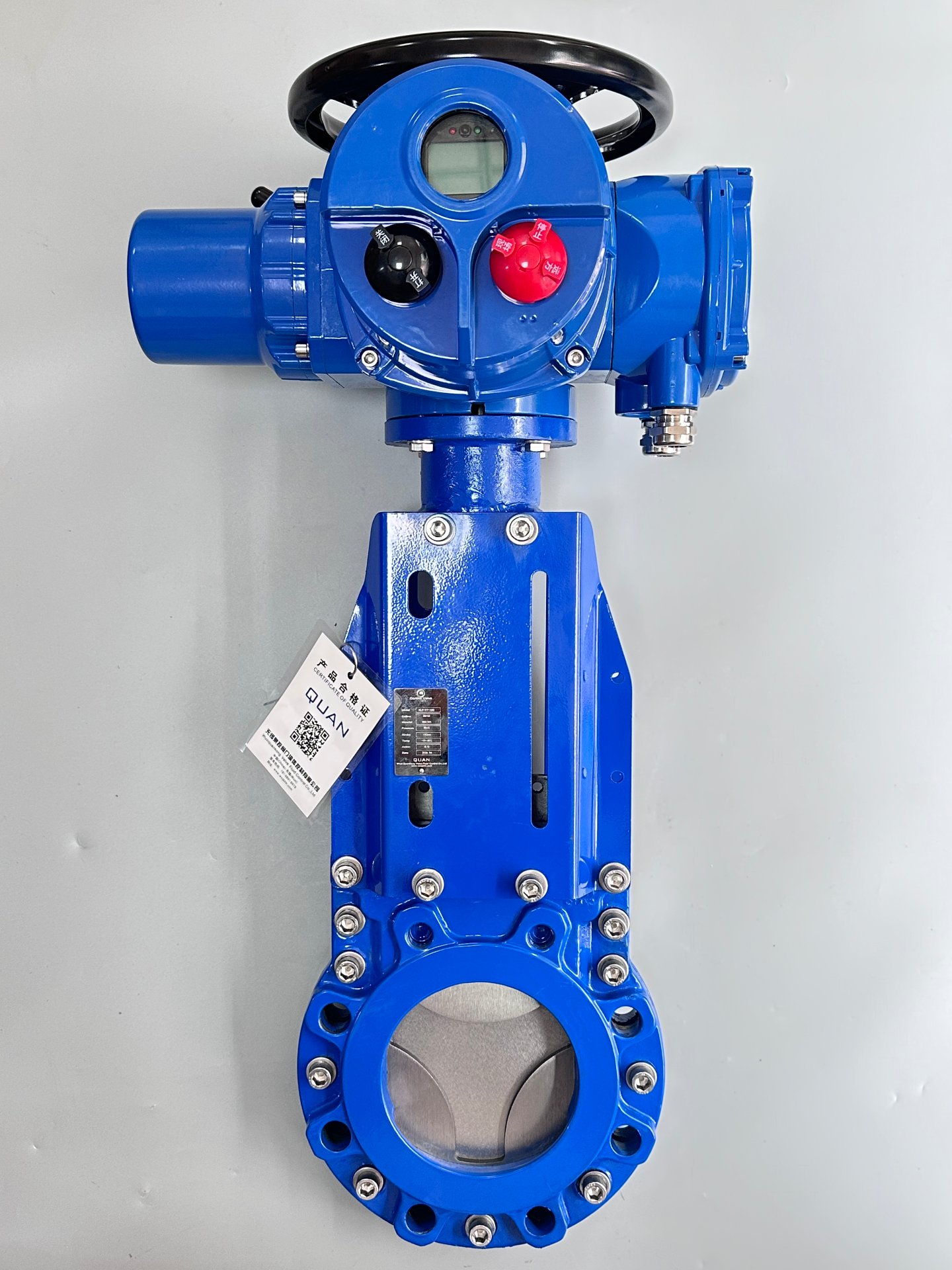 Figure 1: Electric diamond knife gate valve assembly showing the blue modulating actuator with handwheel, position display and local controls
## 2. Why the Diamond Flow Path Helps with Linear Control
The control performance of a modulating valve depends on the relationship between valve travel and effective flow area. When a straight-edged disc gradually opens a circular flow path, the relationship between opening percentage and area is not a simple linear one — especially in the low-opening range, where a small travel change can cause a noticeable flow change.
A diamond-shaped flow path is narrow at the top and bottom and wider in the middle. As the disc moves upward from the closed position, the first exposed flow area is very small, reducing the flow gain in the low-opening region. As the disc continues to rise, the flow area increases according to the design curve, making the entire control process smoother.
That said, a diamond profile does not guarantee perfectly linear flow under all conditions. The valve itself has an inherent flow characteristic; the installed characteristic is further influenced by pipe-network resistance, blower pressure, upstream and downstream differential pressure, pipe diameter, the number of branches and the opening of other valves.
The more precise engineering statement is: the electric diamond knife gate valve optimizes the travel-versus-area relationship so that it delivers a near-linear control characteristic within the design pressure drop and the specified control range. For truly precise control, the valve manufacturer should supply opening-versus-Kv (or Cv) data, and selection should be made against the system resistance curve.
## 3. Why the Diamond Knife Gate Fits Aeration Systems
The primary task of a wastewater aeration system is to deliver the right amount of air to different zones based on the dissolved-oxygen demand of the biological tank. Process load, influent quality, water temperature, sludge concentration and microbial activity all vary continuously — and so does the required airflow.
If each branch line is equipped with nothing more than a manual butterfly valve or a standard knife gate valve, the site must rely on manual adjustment. This creates several problems: adjustment is too slow to follow load changes; the actual valve opening is hard to judge accurately; different aeration branches interfere with one another; the blower operates at an uneconomical point for extended periods; parts of the biological tank may be over-aerated or under-aerated; and the system cannot easily connect to a PLC, DCS or automatic dissolved-oxygen control loop.
When fitted with a modulating electric actuator, the electric diamond knife gate valve can accept 4–20 mA, 0–10 V or digital communication commands and feed the actual position back to the control system. The controller automatically adjusts valve opening based on dissolved oxygen, airflow or pipe pressure — enabling remote control of aeration branches.
The diamond flow path changes relatively gently in the low-opening region, which is well suited to media such as aeration air that require continuous control. Compared with a standard knife gate valve, it reduces abrupt flow changes at small openings. Compared with some butterfly valves, it can deliver a more straightforward travel-versus-control relationship after proper sizing. Compared with a globe-type control valve, its structure is simpler and the flow path is more direct, making it suitable for larger pipe diameters.
## 4. What "Linear" Means in "Electric Linear Control Valve"
In the field, valves with a linear-motion electric actuator are often collectively called electric linear control valves — but this shorthand can be misleading. "Linear" carries at least three meanings:
**1. The actuator output motion is linear.** The electric actuator uses a motor, reduction gear, leadscrew and nut to convert rotary motion into up-and-down linear motion of the disc. The actuator delivers thrust and stroke — not the 90° torque used by typical electric butterfly or ball valves.
**2. The position feedback is roughly proportional to disc travel.** As the control signal changes from 4 mA to 20 mA, the actuator moves the disc from closed to fully open according to a set relationship and continuously feeds back the actual position.
**3. Flow versus opening is near-linear within the design range.** This is what really matters for process control — that a 10% increase in opening produces a relatively steady proportional increase in flow capacity, rather than releasing most of the flow within the first 20% of travel.
It must be stressed that linear actuator travel does not guarantee linear actual flow. When the system pressure drop changes, flow can vary even if the valve opening stays the same. An aeration system is therefore best equipped with an airflow meter, pipe pressure transmitter or dissolved-oxygen probe to form a complete closed loop.
## 5. Comparison with Standard Knife Gate Valves, Butterfly Valves and Globe Control Valves
| Item | Diamond Knife Gate | Standard Knife Gate | Control Butterfly | Globe Control Valve |
|---|---|---|---|---|
| Primary Function | Continuous modulation plus shutoff | Full open or full close | Modulating and shutoff | Precise modulating |
| Flow Path | Diamond or special throttling window | Circular straight-through | Disc rotation changes area | Plug-seat throttling |
| Motion | Linear | Linear | Rotary (quarter-turn) | Linear |
| Low-opening Control | Relatively smooth | Prone to rapid change | Depends on disc profile | Good |
| Solids Handling | Good | Good | Fair | Relatively weak |
| Large-bore Economics | Good | Good | Good | Higher cost |
| Maintenance Difficulty | Medium | Low | Low | High |
| Typical Application | Aeration, wastewater, slurry control | Sludge, slurry shutoff | Water and air control | Steam, gas and process-media fine control |
Selection should not be based on valve price alone. For large-diameter aeration branch lines, the electric diamond knife gate valve offers a good balance of flow capacity, installation footprint, control performance and maintenance cost.
If the process demands very high control precision, a wide turndown ratio or a stringent leakage class, the engineer should compare dedicated control butterfly valves, cage-guided control valves or other options based on calculations — and not default to a knife-gate structure.
## 6. Main Structural Components
**1. Body.** The body contains the line pressure and guides the medium. Common materials include ductile iron, carbon steel, stainless steel and corrosion-resistant alloys selected for the medium. Aeration air is generally not highly corrosive, but the installation environment is humid, so the outer surface must have a reliable anti-corrosion coating. In coastal areas, underground galleries or corrosive atmospheres, the corrosion-resistance class of bolts, stems and exposed parts should be upgraded.
**2. Diamond disc or throttling window.** This is the core component that delivers the valve's modulating characteristic. Design must balance the flow curve, disc strength, media erosion, machining accuracy and shutoff sealing. The diamond profile should not aim only for geometric symmetry — it must be designed against the target Kv, stroke and pressure drop. An opening that is too narrow can cause high velocity, noise and erosion; one that opens too quickly loses the benefit of linear modulation.
**3. Seat.** The seat determines the leakage level after closure. Depending on the medium and temperature, options include rubber, PTFE, reinforced materials or metal-seated designs. An aeration control valve typically prioritizes modulating performance and operating stability over bubble-tight zero leakage. If the valve also serves as a branch isolation valve, however, the allowable leakage must be specified in the procurement technical specification.
**4. Packing and scraper structure.** As the disc moves up and down, the packing prevents media from escaping along the stem or disc passage. For sludge, slurry and fibrous media, the design should also consider scraper, flushing or drain structures to prevent particles from being drawn into the packing zone.
**5. Yoke and leadscrew.** The yoke must withstand the actuator thrust while keeping the leadscrew, disc and body aligned on the same centerline. Insufficient yoke stiffness or misalignment leads to uneven disc wear, travel binding and positioning errors.
**6. Modulating electric actuator.** The actuator typically includes a motor, reduction gear, travel control, thrust protection, position detection, local controls, handwheel and control module. For aeration control, a true modulating actuator should be selected — not a simple on-off unit with only fully-open and fully-closed capability.
## 7. Required Actuator Functions
A suitable modulating electric actuator should offer at minimum: acceptance of 4–20 mA or other continuous control signals; 4–20 mA position feedback output; local/stop/remote mode switching; fully-open and fully-closed limit feedback; over-torque or over-thrust protection; travel limit protection; phase-loss, overheat and motor protection; fail-position setting on signal loss; handwheel emergency operation; position display; and parameter configuration with fault diagnostics.
For outdoor, wet or underground environments, attention must be paid to the ingress protection rating and anti-condensation measures. Where flammable gases may be present, the appropriate explosion-proof actuator must be selected for the hazardous-area classification.
The actuator should not be sized on normal running thrust alone. Allowance must be made for disc-seal friction, breakaway torque after long idle periods, media deposition, pipeline differential pressure and changes in lubrication behavior at low temperatures. A reasonable thrust margin should be maintained, but oversizing should also be avoided — excessive thrust can damage the stem, disc or yoke during a jam.
## 8. How to Select an Aeration Control Valve
An electric diamond knife gate valve should not be selected on pipe diameter alone. At minimum, the following data must be gathered:
**1. Medium conditions.** Confirm whether the medium is air, water, wastewater, sludge or another fluid, and whether it contains particulates, fibers, corrosive constituents or condensate. Aeration air pipes carry air, but condensate can form after shutdown. Water pooling at the lowest point of the valve body can cause corrosion, winter freezing or abnormal disc movement.
**2. Maximum, normal and minimum flow rates.** The control valve must pass the maximum flow while remaining controllable near the minimum flow. Providing only the maximum flow often leads to an oversized valve that runs at very small openings during normal operation.
**3. Upstream and downstream pressures.** Gas flow depends on differential pressure, absolute pressure, temperature and density. An aeration system must also account for the back-pressure from the water depth in the biological tank, diffuser resistance and pipeline friction losses.
**4. Pipe diameter and connection standard.** Specify the DN size, flange standard, pressure class, face-to-face dimension and available installation space. For retrofit projects, also verify the flange bolt-circle diameter and center height of the existing valve.
**5. Control requirements.** Include the control signal, position feedback, communication protocol, fail position, permissible stroking time, modulating frequency and whether the valve connects to a PLC or DCS.
**6. Leakage requirements.** If the valve only performs flow modulation, a reasonable closed-position leakage can be set based on system needs. If it also serves as a maintenance isolation valve, the sealing class must be specified, and the need for a separate dedicated shutoff valve should be evaluated.
**7. Environmental conditions.** Include ambient temperature, humidity, indoor or outdoor installation, ingress protection, hazardous-area classification, corrosion category and power supply.
## 9. Why Valve Size Should Not Match Pipe Size
An aeration main header may be DN500, but that does not mean a DN500 control valve is required. If the normal flow is far below the pipe's design capacity, using a line-size valve may force it to operate at very small openings.
For example, if the valve spends most of its time at 5%–15% opening, it may appear to be controlling — but in reality: a tiny position change causes a large flow change; the actuator constantly corrects, causing valve hunting; the PID loop is hard to tune; local velocity rises, increasing noise and erosion; and the position feedback changes but the actual flow control effect is poor.
Good sizing aims to keep the valve operating in its mid-opening range during normal duty while still accommodating both the maximum flow and the minimum controllable flow. The specific range should be determined from the manufacturer's flow curve — not by mechanically applying a fixed percentage rule.
## 10. Control Strategies in Aeration Systems
**1. Dissolved-oxygen closed-loop control.** A DO probe sends the measurement to the PLC or DCS. The controller compares the setpoint with the actual value and outputs a 4–20 mA signal to adjust the electric diamond knife gate valve opening. This strategy directly targets the biological treatment objective, but DO measurement has inherent lag, so PID parameters should not be set too aggressively.
**2. Airflow closed-loop control.** An airflow meter is installed on the aeration branch, and the controller adjusts the valve opening against a target flow. This approach responds faster and is suitable for distributing air among different tank zones.
**3. DO-plus-flow cascade control.** The outer loop targets dissolved oxygen; the inner loop targets airflow. The outer loop calculates the required air, and the inner loop quickly adjusts the valve opening. This usually yields more stable control but requires more instrumentation and more complex control logic.
**4. Coordinated header-pressure and branch-flow control.** The blower controls the header pressure, while individual aeration-branch valves control distributed flow. Valve adjustments must be coordinated with the blower's VFD or inlet-guide-vane control — otherwise, when multiple branches close simultaneously, the header pressure may rise and risk blower surge.
## 11. PID Tuning and Valve Cycling Frequency
The aeration process has significant inertia. After a valve-position change, air travels from the pipe through the diffuser and then affects the water's dissolved oxygen — this takes time. If the control system chases instantaneous response, the valve will hunt back and forth continuously.
During field commissioning: reduce the proportional gain appropriately; set the integral time based on the tank lag; avoid driving the valve on tiny DO signal fluctuations; set a reasonable control deadband; limit the maximum position change per unit time; apply moderate filtering to the measurement signal; and prevent multiple branches from making large simultaneous moves.
Electric actuators have limits on starts per hour and duty cycle. If the control logic commands the actuator every few seconds, the motor, contactor, brake mechanism and transmission components will wear out prematurely.
## 12. Installation Notes
**1. Ensure correct disc travel direction.** After installation, the disc must have full upward travel clearance. The actuator, yoke or stem must not interfere with platforms, piping or cable trays.
**2. Provide independent support for large actuators.** Large electric diamond knife gate actuators and yokes are heavy and should not rely solely on thin-walled pipe to carry the additional load. Add supports as needed to avoid body distortion and flange leakage.
**3. Tighten flange bolts evenly.** For wafer-style valves, tighten bolts in a diagonal sequence in multiple passes. Non-parallel flanges or uneven bolt loading can distort the clamped body and affect disc movement.
**4. Clean the pipe before installation.** Weld slag, metal chips, sealant debris and other foreign material entering the valve body can score the seat or jam the disc. New piping must be blown clear and cleaned before commissioning.
**5. Electrical and waterproofing.** Use proper waterproof cable glands at all entries; seal unused ports. For outdoor actuators, check the terminal-compartment seal and the heater/anti-condensation device.
**6. Allow maintenance access.** Ensure sufficient space to remove the actuator, packing gland and disc. Designing for installation alone — without considering maintenance — creates major headaches later.
## 13. Commissioning Procedure
Before placing an electric diamond knife gate valve into automatic control, follow this commissioning sequence: inspect the body, yoke, leadscrew and actuator connections; stroke the valve manually through its full travel to confirm no binding; verify the power supply, wiring and motor rotation direction; set the mechanical and electronic travel limits; set the opening and closing thrust protection; calibrate the 0% and 100% positions; apply 4, 8, 12, 16 and 20 mA signals and check the corresponding openings; verify the position feedback signal; test the fully-open, fully-closed and fault-alarm functions; progressively establish the flow-versus-opening relationship under actual pressure; after switching to automatic control, start PID tuning with conservative parameters; and record the final parameters in a commissioning report.
For critical aeration systems, trend curves of valve opening, airflow, header pressure, DO and blower output should be preserved. Trends help reveal whether the valve is oversized, whether PID is over-tuning and whether branches are interfering with each other.
## 14. Common Problems and Solutions
**1. Valve position changes but flow barely responds.** Possible causes: insufficient upstream-downstream pressure drop, blower capacity limit, faulty flow meter, valve operating near fully open for extended periods, or actual Kv not matching the selection. Check position feedback, header pressure, branch flow and blower status together — do not simply blame the valve.
**2. Large flow fluctuations at small openings.** The valve may be oversized, the diamond opening curve may not match the operating conditions, the PID gain may be too high, or the flow-meter range too wide. Switch the loop to manual first, change the valve position stepwise and observe actual flow before deciding whether the problem is the valve characteristic or the control parameters.
**3. Disc binding during travel.** Common causes: disc misalignment, over-tightened packing, media deposition, flange clamping distortion, lack of leadscrew lubrication or yoke misalignment. Do not simply increase actuator thrust — forcing it can damage the leadscrew, disc or yoke.
**4. Frequent actuator over-torque alarms.** Check for disc jamming, thrust setting too low, incorrect travel limits and over-tightening at the closed position. Also verify that the actuator was sized for the worst-case conditions.
**5. Leakage after valve closure.** Possible causes: worn seat, trapped foreign material, disc not fully closed or the sealing design is fundamentally unsuited to tight shutoff. Judge against the leakage class agreed at purchase — a modulating valve's actual performance should not be used to substitute for an isolation valve's requirement.
**6. Unstable position feedback.** Inspect the position sensor, wiring shielding, power supply quality, feedback linkage play and actuator parameters. If the position is steady but feedback fluctuates, troubleshoot the electrical signal first; if the position itself varies, check the control loop.
**7. Excessive operating noise.** Aeration air passing through a narrow flow path at high differential pressure and small opening can reach very high velocity, causing aerodynamic noise. Verify the valve size, pressure drop, opening and allowable velocity — if necessary, optimize the piping or adopt a staged pressure-reduction scheme.
## 15. Key Maintenance Points
Maintenance of an electric diamond knife gate valve must go beyond the actuator. The body, disc, packing, leadscrew and control signals all need scheduled attention.
Recommended periodic checks: disc surface for erosion, wear and deformation; seat for damage or buildup; packing area for external leakage; leadscrew lubrication; yoke and connection bolts for looseness; actuator over-torque history; position feedback accuracy; handwheel changeover mechanism reliability; cable entry for water ingress; and whether the opening-versus-flow relationship has shifted.
If the aeration medium produces significant condensate, check the pipe drains regularly. For sludge and slurry service, increase the flushing or cleaning frequency based on the deposition rate.
## 16. Service Conditions to Approach with Caution
While the electric diamond knife gate valve has a broad application scope, it is not a universal control valve. The following conditions require careful evaluation: very high control precision requirements; extremely high pressure drops; high-temperature high-pressure steam; severe cavitation or flashing liquids; strict zero-leakage shutoff; highly corrosive media with difficult material selection; large volumes of sharp hard particles at high velocity; very high-frequency continuous cycling; extremely wide flow range requirements; and strict limits on aerodynamic noise.
For these cases, compare specialized control valves, abrasion-resistant valves, control butterfly valves or multi-stage pressure-reduction designs before making a decision.
## 17. What to Confirm with the Manufacturer Before Purchase
To avoid "it opens and closes, but it does not modulate well," the procurement specification should clearly state: valve size, pressure class and connection standard; maximum, normal and minimum flow rates; design and operating temperatures; upstream pressure, downstream pressure and maximum differential pressure; medium composition and solids content; valve Kv or Cv curve; design flow characteristic; recommended operating opening range; allowable leakage; body, disc and seat materials; actuator rated thrust and modulating duty cycle; control signal and feedback signal; ingress protection and explosion-proof classification; permissible starting frequency; fail position on power or signal loss; and factory stroking test and flow-characteristic documentation.
For aeration control valve projects, it is best to have the manufacturer perform the sizing against the actual operating conditions — rather than simply sending out a pipe-diameter table for quotation.
## 18. Engineering Value
In the operating costs of a wastewater treatment plant, the aeration system is typically one of the largest energy consumers. Poor valve control leads to elevated blower pressure, uneven air distribution and unstable dissolved-oxygen control.
Upgrading from manual or simple on-off valves to electric diamond knife gate valves can deliver: remote automatic control of aeration branches; improved air-distribution controllability; reduced manual adjustment; energy-saving operation coordinated with blower VFD control; more stable dissolved oxygen; recorded position and flow data; easier diagnosis of diffuser clogging and pipe-network anomalies; and a higher level of automation for the water-treatment system.
These benefits do not come from a single valve alone. The valve, flow meter, DO probe, control logic, blower and diffusers must be engineered as a complete, coordinated system.
## 19. Closing Remarks
The electric diamond knife gate valve is not simply a standard knife gate valve with an electric actuator bolted on. Its core value lies in using a diamond-shaped throttling flow path to improve the relationship between travel and flow area, together with a modulating electric actuator that delivers continuous positioning.
In aeration systems, a properly sized electric diamond knife gate valve can serve as an electric linear control valve, handling air-branch flow distribution and dissolved-oxygen control. But practical engineering must correctly understand what "linear" means: linear disc travel is only the foundation — actual flow characteristics also depend on the valve's internal geometry, the system pressure drop and the pipe-network resistance.
Before selection, complete data on the medium, flow rates, pressures, temperature, control signals and installation conditions must be provided. During commissioning, the relationship between valve position and actual flow should be established. After commissioning, trend data should be used to optimize PID parameters and maintenance intervals. Only when valve sizing, actuator, instrumentation and control logic are well matched can the aeration control valve deliver its full value.
---
*This article is written by the technical engineering team of Wuxi Quankong Valve & Fluid Control Co., Ltd. (QUAN). Industrial valves | actuator packages | fluid control solutions. Technical inquiries: [email protected]*
Figure 1: Electric diamond knife gate valve assembly showing the blue modulating actuator with handwheel, position display and local controls
## 2. Why the Diamond Flow Path Helps with Linear Control
The control performance of a modulating valve depends on the relationship between valve travel and effective flow area. When a straight-edged disc gradually opens a circular flow path, the relationship between opening percentage and area is not a simple linear one — especially in the low-opening range, where a small travel change can cause a noticeable flow change.
A diamond-shaped flow path is narrow at the top and bottom and wider in the middle. As the disc moves upward from the closed position, the first exposed flow area is very small, reducing the flow gain in the low-opening region. As the disc continues to rise, the flow area increases according to the design curve, making the entire control process smoother.
That said, a diamond profile does not guarantee perfectly linear flow under all conditions. The valve itself has an inherent flow characteristic; the installed characteristic is further influenced by pipe-network resistance, blower pressure, upstream and downstream differential pressure, pipe diameter, the number of branches and the opening of other valves.
The more precise engineering statement is: the electric diamond knife gate valve optimizes the travel-versus-area relationship so that it delivers a near-linear control characteristic within the design pressure drop and the specified control range. For truly precise control, the valve manufacturer should supply opening-versus-Kv (or Cv) data, and selection should be made against the system resistance curve.
## 3. Why the Diamond Knife Gate Fits Aeration Systems
The primary task of a wastewater aeration system is to deliver the right amount of air to different zones based on the dissolved-oxygen demand of the biological tank. Process load, influent quality, water temperature, sludge concentration and microbial activity all vary continuously — and so does the required airflow.
If each branch line is equipped with nothing more than a manual butterfly valve or a standard knife gate valve, the site must rely on manual adjustment. This creates several problems: adjustment is too slow to follow load changes; the actual valve opening is hard to judge accurately; different aeration branches interfere with one another; the blower operates at an uneconomical point for extended periods; parts of the biological tank may be over-aerated or under-aerated; and the system cannot easily connect to a PLC, DCS or automatic dissolved-oxygen control loop.
When fitted with a modulating electric actuator, the electric diamond knife gate valve can accept 4–20 mA, 0–10 V or digital communication commands and feed the actual position back to the control system. The controller automatically adjusts valve opening based on dissolved oxygen, airflow or pipe pressure — enabling remote control of aeration branches.
The diamond flow path changes relatively gently in the low-opening region, which is well suited to media such as aeration air that require continuous control. Compared with a standard knife gate valve, it reduces abrupt flow changes at small openings. Compared with some butterfly valves, it can deliver a more straightforward travel-versus-control relationship after proper sizing. Compared with a globe-type control valve, its structure is simpler and the flow path is more direct, making it suitable for larger pipe diameters.
## 4. What "Linear" Means in "Electric Linear Control Valve"
In the field, valves with a linear-motion electric actuator are often collectively called electric linear control valves — but this shorthand can be misleading. "Linear" carries at least three meanings:
**1. The actuator output motion is linear.** The electric actuator uses a motor, reduction gear, leadscrew and nut to convert rotary motion into up-and-down linear motion of the disc. The actuator delivers thrust and stroke — not the 90° torque used by typical electric butterfly or ball valves.
**2. The position feedback is roughly proportional to disc travel.** As the control signal changes from 4 mA to 20 mA, the actuator moves the disc from closed to fully open according to a set relationship and continuously feeds back the actual position.
**3. Flow versus opening is near-linear within the design range.** This is what really matters for process control — that a 10% increase in opening produces a relatively steady proportional increase in flow capacity, rather than releasing most of the flow within the first 20% of travel.
It must be stressed that linear actuator travel does not guarantee linear actual flow. When the system pressure drop changes, flow can vary even if the valve opening stays the same. An aeration system is therefore best equipped with an airflow meter, pipe pressure transmitter or dissolved-oxygen probe to form a complete closed loop.
## 5. Comparison with Standard Knife Gate Valves, Butterfly Valves and Globe Control Valves
| Item | Diamond Knife Gate | Standard Knife Gate | Control Butterfly | Globe Control Valve |
|---|---|---|---|---|
| Primary Function | Continuous modulation plus shutoff | Full open or full close | Modulating and shutoff | Precise modulating |
| Flow Path | Diamond or special throttling window | Circular straight-through | Disc rotation changes area | Plug-seat throttling |
| Motion | Linear | Linear | Rotary (quarter-turn) | Linear |
| Low-opening Control | Relatively smooth | Prone to rapid change | Depends on disc profile | Good |
| Solids Handling | Good | Good | Fair | Relatively weak |
| Large-bore Economics | Good | Good | Good | Higher cost |
| Maintenance Difficulty | Medium | Low | Low | High |
| Typical Application | Aeration, wastewater, slurry control | Sludge, slurry shutoff | Water and air control | Steam, gas and process-media fine control |
Selection should not be based on valve price alone. For large-diameter aeration branch lines, the electric diamond knife gate valve offers a good balance of flow capacity, installation footprint, control performance and maintenance cost.
If the process demands very high control precision, a wide turndown ratio or a stringent leakage class, the engineer should compare dedicated control butterfly valves, cage-guided control valves or other options based on calculations — and not default to a knife-gate structure.
## 6. Main Structural Components
**1. Body.** The body contains the line pressure and guides the medium. Common materials include ductile iron, carbon steel, stainless steel and corrosion-resistant alloys selected for the medium. Aeration air is generally not highly corrosive, but the installation environment is humid, so the outer surface must have a reliable anti-corrosion coating. In coastal areas, underground galleries or corrosive atmospheres, the corrosion-resistance class of bolts, stems and exposed parts should be upgraded.
**2. Diamond disc or throttling window.** This is the core component that delivers the valve's modulating characteristic. Design must balance the flow curve, disc strength, media erosion, machining accuracy and shutoff sealing. The diamond profile should not aim only for geometric symmetry — it must be designed against the target Kv, stroke and pressure drop. An opening that is too narrow can cause high velocity, noise and erosion; one that opens too quickly loses the benefit of linear modulation.
**3. Seat.** The seat determines the leakage level after closure. Depending on the medium and temperature, options include rubber, PTFE, reinforced materials or metal-seated designs. An aeration control valve typically prioritizes modulating performance and operating stability over bubble-tight zero leakage. If the valve also serves as a branch isolation valve, however, the allowable leakage must be specified in the procurement technical specification.
**4. Packing and scraper structure.** As the disc moves up and down, the packing prevents media from escaping along the stem or disc passage. For sludge, slurry and fibrous media, the design should also consider scraper, flushing or drain structures to prevent particles from being drawn into the packing zone.
**5. Yoke and leadscrew.** The yoke must withstand the actuator thrust while keeping the leadscrew, disc and body aligned on the same centerline. Insufficient yoke stiffness or misalignment leads to uneven disc wear, travel binding and positioning errors.
**6. Modulating electric actuator.** The actuator typically includes a motor, reduction gear, travel control, thrust protection, position detection, local controls, handwheel and control module. For aeration control, a true modulating actuator should be selected — not a simple on-off unit with only fully-open and fully-closed capability.
## 7. Required Actuator Functions
A suitable modulating electric actuator should offer at minimum: acceptance of 4–20 mA or other continuous control signals; 4–20 mA position feedback output; local/stop/remote mode switching; fully-open and fully-closed limit feedback; over-torque or over-thrust protection; travel limit protection; phase-loss, overheat and motor protection; fail-position setting on signal loss; handwheel emergency operation; position display; and parameter configuration with fault diagnostics.
For outdoor, wet or underground environments, attention must be paid to the ingress protection rating and anti-condensation measures. Where flammable gases may be present, the appropriate explosion-proof actuator must be selected for the hazardous-area classification.
The actuator should not be sized on normal running thrust alone. Allowance must be made for disc-seal friction, breakaway torque after long idle periods, media deposition, pipeline differential pressure and changes in lubrication behavior at low temperatures. A reasonable thrust margin should be maintained, but oversizing should also be avoided — excessive thrust can damage the stem, disc or yoke during a jam.
## 8. How to Select an Aeration Control Valve
An electric diamond knife gate valve should not be selected on pipe diameter alone. At minimum, the following data must be gathered:
**1. Medium conditions.** Confirm whether the medium is air, water, wastewater, sludge or another fluid, and whether it contains particulates, fibers, corrosive constituents or condensate. Aeration air pipes carry air, but condensate can form after shutdown. Water pooling at the lowest point of the valve body can cause corrosion, winter freezing or abnormal disc movement.
**2. Maximum, normal and minimum flow rates.** The control valve must pass the maximum flow while remaining controllable near the minimum flow. Providing only the maximum flow often leads to an oversized valve that runs at very small openings during normal operation.
**3. Upstream and downstream pressures.** Gas flow depends on differential pressure, absolute pressure, temperature and density. An aeration system must also account for the back-pressure from the water depth in the biological tank, diffuser resistance and pipeline friction losses.
**4. Pipe diameter and connection standard.** Specify the DN size, flange standard, pressure class, face-to-face dimension and available installation space. For retrofit projects, also verify the flange bolt-circle diameter and center height of the existing valve.
**5. Control requirements.** Include the control signal, position feedback, communication protocol, fail position, permissible stroking time, modulating frequency and whether the valve connects to a PLC or DCS.
**6. Leakage requirements.** If the valve only performs flow modulation, a reasonable closed-position leakage can be set based on system needs. If it also serves as a maintenance isolation valve, the sealing class must be specified, and the need for a separate dedicated shutoff valve should be evaluated.
**7. Environmental conditions.** Include ambient temperature, humidity, indoor or outdoor installation, ingress protection, hazardous-area classification, corrosion category and power supply.
## 9. Why Valve Size Should Not Match Pipe Size
An aeration main header may be DN500, but that does not mean a DN500 control valve is required. If the normal flow is far below the pipe's design capacity, using a line-size valve may force it to operate at very small openings.
For example, if the valve spends most of its time at 5%–15% opening, it may appear to be controlling — but in reality: a tiny position change causes a large flow change; the actuator constantly corrects, causing valve hunting; the PID loop is hard to tune; local velocity rises, increasing noise and erosion; and the position feedback changes but the actual flow control effect is poor.
Good sizing aims to keep the valve operating in its mid-opening range during normal duty while still accommodating both the maximum flow and the minimum controllable flow. The specific range should be determined from the manufacturer's flow curve — not by mechanically applying a fixed percentage rule.
## 10. Control Strategies in Aeration Systems
**1. Dissolved-oxygen closed-loop control.** A DO probe sends the measurement to the PLC or DCS. The controller compares the setpoint with the actual value and outputs a 4–20 mA signal to adjust the electric diamond knife gate valve opening. This strategy directly targets the biological treatment objective, but DO measurement has inherent lag, so PID parameters should not be set too aggressively.
**2. Airflow closed-loop control.** An airflow meter is installed on the aeration branch, and the controller adjusts the valve opening against a target flow. This approach responds faster and is suitable for distributing air among different tank zones.
**3. DO-plus-flow cascade control.** The outer loop targets dissolved oxygen; the inner loop targets airflow. The outer loop calculates the required air, and the inner loop quickly adjusts the valve opening. This usually yields more stable control but requires more instrumentation and more complex control logic.
**4. Coordinated header-pressure and branch-flow control.** The blower controls the header pressure, while individual aeration-branch valves control distributed flow. Valve adjustments must be coordinated with the blower's VFD or inlet-guide-vane control — otherwise, when multiple branches close simultaneously, the header pressure may rise and risk blower surge.
## 11. PID Tuning and Valve Cycling Frequency
The aeration process has significant inertia. After a valve-position change, air travels from the pipe through the diffuser and then affects the water's dissolved oxygen — this takes time. If the control system chases instantaneous response, the valve will hunt back and forth continuously.
During field commissioning: reduce the proportional gain appropriately; set the integral time based on the tank lag; avoid driving the valve on tiny DO signal fluctuations; set a reasonable control deadband; limit the maximum position change per unit time; apply moderate filtering to the measurement signal; and prevent multiple branches from making large simultaneous moves.
Electric actuators have limits on starts per hour and duty cycle. If the control logic commands the actuator every few seconds, the motor, contactor, brake mechanism and transmission components will wear out prematurely.
## 12. Installation Notes
**1. Ensure correct disc travel direction.** After installation, the disc must have full upward travel clearance. The actuator, yoke or stem must not interfere with platforms, piping or cable trays.
**2. Provide independent support for large actuators.** Large electric diamond knife gate actuators and yokes are heavy and should not rely solely on thin-walled pipe to carry the additional load. Add supports as needed to avoid body distortion and flange leakage.
**3. Tighten flange bolts evenly.** For wafer-style valves, tighten bolts in a diagonal sequence in multiple passes. Non-parallel flanges or uneven bolt loading can distort the clamped body and affect disc movement.
**4. Clean the pipe before installation.** Weld slag, metal chips, sealant debris and other foreign material entering the valve body can score the seat or jam the disc. New piping must be blown clear and cleaned before commissioning.
**5. Electrical and waterproofing.** Use proper waterproof cable glands at all entries; seal unused ports. For outdoor actuators, check the terminal-compartment seal and the heater/anti-condensation device.
**6. Allow maintenance access.** Ensure sufficient space to remove the actuator, packing gland and disc. Designing for installation alone — without considering maintenance — creates major headaches later.
## 13. Commissioning Procedure
Before placing an electric diamond knife gate valve into automatic control, follow this commissioning sequence: inspect the body, yoke, leadscrew and actuator connections; stroke the valve manually through its full travel to confirm no binding; verify the power supply, wiring and motor rotation direction; set the mechanical and electronic travel limits; set the opening and closing thrust protection; calibrate the 0% and 100% positions; apply 4, 8, 12, 16 and 20 mA signals and check the corresponding openings; verify the position feedback signal; test the fully-open, fully-closed and fault-alarm functions; progressively establish the flow-versus-opening relationship under actual pressure; after switching to automatic control, start PID tuning with conservative parameters; and record the final parameters in a commissioning report.
For critical aeration systems, trend curves of valve opening, airflow, header pressure, DO and blower output should be preserved. Trends help reveal whether the valve is oversized, whether PID is over-tuning and whether branches are interfering with each other.
## 14. Common Problems and Solutions
**1. Valve position changes but flow barely responds.** Possible causes: insufficient upstream-downstream pressure drop, blower capacity limit, faulty flow meter, valve operating near fully open for extended periods, or actual Kv not matching the selection. Check position feedback, header pressure, branch flow and blower status together — do not simply blame the valve.
**2. Large flow fluctuations at small openings.** The valve may be oversized, the diamond opening curve may not match the operating conditions, the PID gain may be too high, or the flow-meter range too wide. Switch the loop to manual first, change the valve position stepwise and observe actual flow before deciding whether the problem is the valve characteristic or the control parameters.
**3. Disc binding during travel.** Common causes: disc misalignment, over-tightened packing, media deposition, flange clamping distortion, lack of leadscrew lubrication or yoke misalignment. Do not simply increase actuator thrust — forcing it can damage the leadscrew, disc or yoke.
**4. Frequent actuator over-torque alarms.** Check for disc jamming, thrust setting too low, incorrect travel limits and over-tightening at the closed position. Also verify that the actuator was sized for the worst-case conditions.
**5. Leakage after valve closure.** Possible causes: worn seat, trapped foreign material, disc not fully closed or the sealing design is fundamentally unsuited to tight shutoff. Judge against the leakage class agreed at purchase — a modulating valve's actual performance should not be used to substitute for an isolation valve's requirement.
**6. Unstable position feedback.** Inspect the position sensor, wiring shielding, power supply quality, feedback linkage play and actuator parameters. If the position is steady but feedback fluctuates, troubleshoot the electrical signal first; if the position itself varies, check the control loop.
**7. Excessive operating noise.** Aeration air passing through a narrow flow path at high differential pressure and small opening can reach very high velocity, causing aerodynamic noise. Verify the valve size, pressure drop, opening and allowable velocity — if necessary, optimize the piping or adopt a staged pressure-reduction scheme.
## 15. Key Maintenance Points
Maintenance of an electric diamond knife gate valve must go beyond the actuator. The body, disc, packing, leadscrew and control signals all need scheduled attention.
Recommended periodic checks: disc surface for erosion, wear and deformation; seat for damage or buildup; packing area for external leakage; leadscrew lubrication; yoke and connection bolts for looseness; actuator over-torque history; position feedback accuracy; handwheel changeover mechanism reliability; cable entry for water ingress; and whether the opening-versus-flow relationship has shifted.
If the aeration medium produces significant condensate, check the pipe drains regularly. For sludge and slurry service, increase the flushing or cleaning frequency based on the deposition rate.
## 16. Service Conditions to Approach with Caution
While the electric diamond knife gate valve has a broad application scope, it is not a universal control valve. The following conditions require careful evaluation: very high control precision requirements; extremely high pressure drops; high-temperature high-pressure steam; severe cavitation or flashing liquids; strict zero-leakage shutoff; highly corrosive media with difficult material selection; large volumes of sharp hard particles at high velocity; very high-frequency continuous cycling; extremely wide flow range requirements; and strict limits on aerodynamic noise.
For these cases, compare specialized control valves, abrasion-resistant valves, control butterfly valves or multi-stage pressure-reduction designs before making a decision.
## 17. What to Confirm with the Manufacturer Before Purchase
To avoid "it opens and closes, but it does not modulate well," the procurement specification should clearly state: valve size, pressure class and connection standard; maximum, normal and minimum flow rates; design and operating temperatures; upstream pressure, downstream pressure and maximum differential pressure; medium composition and solids content; valve Kv or Cv curve; design flow characteristic; recommended operating opening range; allowable leakage; body, disc and seat materials; actuator rated thrust and modulating duty cycle; control signal and feedback signal; ingress protection and explosion-proof classification; permissible starting frequency; fail position on power or signal loss; and factory stroking test and flow-characteristic documentation.
For aeration control valve projects, it is best to have the manufacturer perform the sizing against the actual operating conditions — rather than simply sending out a pipe-diameter table for quotation.
## 18. Engineering Value
In the operating costs of a wastewater treatment plant, the aeration system is typically one of the largest energy consumers. Poor valve control leads to elevated blower pressure, uneven air distribution and unstable dissolved-oxygen control.
Upgrading from manual or simple on-off valves to electric diamond knife gate valves can deliver: remote automatic control of aeration branches; improved air-distribution controllability; reduced manual adjustment; energy-saving operation coordinated with blower VFD control; more stable dissolved oxygen; recorded position and flow data; easier diagnosis of diffuser clogging and pipe-network anomalies; and a higher level of automation for the water-treatment system.
These benefits do not come from a single valve alone. The valve, flow meter, DO probe, control logic, blower and diffusers must be engineered as a complete, coordinated system.
## 19. Closing Remarks
The electric diamond knife gate valve is not simply a standard knife gate valve with an electric actuator bolted on. Its core value lies in using a diamond-shaped throttling flow path to improve the relationship between travel and flow area, together with a modulating electric actuator that delivers continuous positioning.
In aeration systems, a properly sized electric diamond knife gate valve can serve as an electric linear control valve, handling air-branch flow distribution and dissolved-oxygen control. But practical engineering must correctly understand what "linear" means: linear disc travel is only the foundation — actual flow characteristics also depend on the valve's internal geometry, the system pressure drop and the pipe-network resistance.
Before selection, complete data on the medium, flow rates, pressures, temperature, control signals and installation conditions must be provided. During commissioning, the relationship between valve position and actual flow should be established. After commissioning, trend data should be used to optimize PID parameters and maintenance intervals. Only when valve sizing, actuator, instrumentation and control logic are well matched can the aeration control valve deliver its full value.
---
*This article is written by the technical engineering team of Wuxi Quankong Valve & Fluid Control Co., Ltd. (QUAN). Industrial valves | actuator packages | fluid control solutions. Technical inquiries: [email protected]*
Figure 1: Electric diamond knife gate valve assembly showing the blue modulating actuator with handwheel, position display and local controls
# 电动菱形刀闸阀在曝气系统中的应用:电动线性调节阀原理、选型与调试
在污水处理、生物发酵、工业供气以及部分粉体输送系统中,管道不仅需要完成开启和关闭,还要根据工艺负荷连续调整介质流量。普通刀闸阀更适合全开、全关工况,如果长期停留在小开度位置,容易出现流量变化过快、阀板振动、局部冲刷和控制不稳定等问题。
电动菱形刀闸阀是在传统刀闸阀基础上发展起来的一种调节型阀门。它通过特殊设计的菱形流道,使阀门有效流通面积随阀板行程逐步变化,再配合调节型电动执行机构,实现对空气、水、低浓度污泥以及部分含固介质的连续控制。
在水处理曝气系统中,这种阀门也常被称为电动线性调节阀、曝气调节阀或电动菱形调节刀闸阀。需要说明的是,"线性"并不只是指阀杆作直线运动,更重要的是阀门在规定工况下能够获得接近线性的流量变化特性。
## 一、什么是电动菱形刀闸阀
电动菱形刀闸阀主要由阀体、阀板、菱形流道、阀座、填料密封、支架、丝杆传动机构和调节型电动执行机构组成。
普通刀闸阀的流道通常为圆形,阀板由上向下直接切断整个通道。阀门刚开始开启时,圆形流道底部会迅速形成较大的流通面积,导致小行程对应较大的流量变化,因此不容易进行精细调节。
菱形刀闸阀则通过对阀板边缘、流道窗口或者节流部件进行专门设计,使流通面积按照预定规律增加。阀门从关闭位置逐渐开启时,先形成较小的节流通道,随着阀板继续上升,通道面积平稳扩大。
从外观上看,电动菱形刀闸阀与普通电动刀闸阀较为接近,但两者的设计目的不同。普通刀闸阀重点考虑可靠切断和含固介质通过能力,菱形刀闸阀则要同时考虑流量特性、调节稳定性、阀板刚度、密封性能和执行机构定位精度。
图1:电动菱形刀闸阀整体结构(蓝色调节型电动执行器,配手轮、阀位显示及就地操作按钮)
## 二、菱形流道为什么有利于线性调节
调节阀的控制效果,取决于阀门行程与有效流通面积之间的关系。普通圆形流道被直线阀板逐步打开时,开度与面积之间并不是简单的线性关系,尤其在低开度区域,少量行程变化就可能引起较明显的流量变化。
菱形流道的上下两端较窄,中间逐渐变宽。阀板从关闭位置向上移动时,最先露出的流通区域很小,能够降低低开度阶段的流量增幅。阀板继续上升后,流通面积按设计规律增加,使整个调节过程更加平缓。
不过,菱形结构并不意味着阀门在所有工况下都能获得绝对线性的流量。阀门本身具有的是固有流量特性,实际安装后的流量特性还会受到管网阻力、风机压力、上下游压差、管径、支路数量以及其他阀门开度的影响。
因此,工程上更准确的说法是:电动菱形刀闸阀通过优化行程与流通面积的关系,使其在设计压差和规定控制范围内获得接近线性的调节特性。真正用于精确控制时,应由阀门厂家提供开度与 Kv 值或 Cv 值的对应数据,并结合系统阻力曲线进行选型。
## 三、电动菱形刀闸阀为什么适合曝气系统
污水处理曝气系统的主要任务,是根据生化池的溶解氧需求向不同区域输送适量空气。工艺负荷、进水水质、水温、污泥浓度和微生物活性不断变化,所需曝气量也随之变化。
如果各支路只安装普通手动蝶阀或普通刀闸阀,现场通常依靠人工调整开度。这种方式存在几个明显问题:调整速度慢,无法及时跟随负荷变化;阀门实际开度不容易准确判断;不同曝气支路之间容易相互影响;鼓风机长期处于不经济的工作状态;生化池可能出现局部曝气过量或曝气不足;难以接入 PLC、DCS 或溶解氧自动控制系统。
电动菱形刀闸阀配备调节型电动执行机构后,可以接收 4~20mA、0~10V 或数字通信指令,并将实际阀位反馈给控制系统。控制器根据溶解氧、空气流量或管道压力自动调整阀门开度,从而实现曝气支路的远程控制。
菱形流道在小开度区域变化较平缓,特别适合曝气空气这种需要连续控制的介质。相比普通刀闸阀,它可以减少低开度时的流量突变;相比某些蝶阀,它在合理选型后能够获得更直观的行程控制关系;相比截止式调节阀,其结构相对简单,流道更直接,适合较大口径管道。
## 四、"电动线性调节阀"中的线性是什么意思
现场经常把带直行程电动执行机构的阀门统称为电动线性调节阀,但这种叫法容易产生误解。线性至少包含三层含义:
**1. 执行机构的输出运动为直线。** 电动执行器通过电机、减速机构、丝杆和螺母,将旋转运动转换为阀板的上下直线运动。执行器输出的是推力和行程,而不是普通电动蝶阀、球阀使用的 90° 转矩。
**2. 阀位反馈与阀板行程基本成比例。** 当控制信号从 4mA 变化到 20mA 时,执行机构能够按照设定关系将阀板从关闭位置移动到全开位置,并连续反馈实际开度。
**3. 流量与开度在设计范围内接近线性。** 这才是工艺控制真正关心的内容。即阀门开度增加 10%,流量能力也按照相对稳定的比例增加,而不是在前 20% 行程内就释放大部分流量。
需要强调的是,执行器行程线性并不等于实际流量必然线性。系统压差发生变化时,即使阀门开度保持不变,流量也可能变化。因此,曝气系统最好同时配置空气流量计、管道压力变送器或溶解氧仪,形成完整的闭环控制。
## 五、与普通刀闸阀、蝶阀和调节阀的区别
| 对比项目 | 电动菱形刀闸阀 | 普通刀闸阀 | 调节蝶阀 | 截止式调节阀 |
|---|---|---|---|---|
| 主要功能 | 连续调节兼顾切断 | 全开或全关 | 调节和切断 | 精确调节 |
| 流道特点 | 菱形或特殊节流窗口 | 圆形直通流道 | 蝶板旋转改变面积 | 阀芯阀座节流 |
| 运动形式 | 直线运动 | 直线运动 | 角行程 | 直线运动 |
| 低开度控制 | 相对平缓 | 容易变化过快 | 取决于蝶板结构 | 较好 |
| 含固介质能力 | 较好 | 较好 | 一般 | 相对较弱 |
| 大口径经济性 | 较好 | 好 | 好 | 成本较高 |
| 维护难度 | 中等 | 较低 | 较低 | 较高 |
| 典型应用 | 曝气、污水、浆料调节 | 污泥、矿浆切断 | 水和空气调节 | 蒸汽、气体及工艺介质精调 |
选择时不能只比较阀门价格。对于大口径曝气支管,电动菱形刀闸阀在流量能力、安装空间、控制性能和维护成本之间具有较好的平衡。
如果工艺要求极高的控制精度、很大的可调比或严格的泄漏等级,则应根据计算结果比较专用调节蝶阀、套筒调节阀或其他控制阀,不能一概使用刀闸结构。
## 六、电动菱形刀闸阀的主要结构
**1. 阀体。** 阀体承担管道压力并引导介质通过。常用材质包括球墨铸铁、碳钢、不锈钢以及根据介质要求选用的耐腐蚀材料。污水处理曝气空气通常腐蚀性不强,但安装环境潮湿,阀体外表面应采用可靠的防腐涂层。沿海地区、地下管廊、腐蚀性气体环境还应提高螺栓、阀杆和外露零件的耐腐蚀等级。
**2. 菱形阀板或节流窗口。** 这是阀门实现调节特性的核心部件。设计时需要综合考虑流量曲线、阀板强度、介质冲刷、加工精度和关闭密封。菱形轮廓不能只追求外形对称,还要根据目标 Kv 值、行程和压差进行设计。开口过窄可能导致高流速、噪声和冲刷;开口变化过快又会失去线性调节的意义。
**3. 阀座。** 阀座决定关闭后的泄漏水平。根据介质和温度,可采用橡胶、聚四氟乙烯、增强材料或金属密封结构。曝气调节阀通常更重视调节性能和运行稳定性,不一定要求达到气泡级零泄漏。但若阀门同时承担支路隔离功能,应在采购技术条件中明确允许泄漏量。
**4. 填料与刮料结构。** 阀板上下运动时,填料负责防止介质从阀杆或阀板通道外漏。对于污泥、浆料和含纤维介质,还应考虑刮料、冲洗或排污结构,防止颗粒被带入填料区。
**5. 支架和传动丝杆。** 支架需要承受执行器推力,同时保证丝杆、阀板和阀体中心一致。支架刚度不足或同轴度偏差,会造成阀板偏磨、行程卡涩和定位误差。
**6. 调节型电动执行器。** 执行器一般包含电机、减速机构、行程控制、推力保护、位置检测、就地操作、手轮和控制模块。用于曝气调节时,应选择真正的调节型执行器,而不是只具备全开、全关功能的开关型产品。
## 七、电动执行机构应具备哪些功能
一台合适的调节型电动执行器,至少应具备以下功能:接收 4~20mA 或其他连续控制信号;输出 4~20mA 阀位反馈;就地、停止、远程模式切换;开到位和关到位反馈;过力矩或过推力保护;行程限位保护;缺相、过热和电机保护;断信号故障位置设定;手轮应急操作;阀位显示;参数设置和故障诊断。
对于户外、潮湿或地下环境,应关注防护等级和防凝露措施。存在可燃气体时,需要根据危险区域等级选择相应的防爆执行机构。
执行器不能只按阀门正常运行推力选择。还要考虑阀板密封摩擦、长期停用后的启动阻力、介质沉积、管道压差以及低温条件下润滑性能变化。一般应保留合理的推力裕量,但也不能盲目放大,否则可能在卡阻时损坏阀杆、阀板或支架。
## 八、曝气调节阀如何进行选型
电动菱形刀闸阀不能只根据管道口径直接选型。至少需要收集以下数据:
**1. 介质条件。** 明确介质为空气、水、污水、污泥还是其他流体,并确认是否含颗粒、纤维、腐蚀性成分和冷凝水。曝气空气管道虽然输送的是空气,但停机后可能产生冷凝水。阀体最低处若长期积水,会造成腐蚀、冬季冻结或阀板动作异常。
**2. 最大、正常和最小流量。** 调节阀不仅要通过最大流量,还要在最小流量附近保持可控。只提供最大流量,往往会导致阀门选得过大,正常运行时长期停留在小开度区域。
**3. 上下游压力。** 气体流量与压差、绝对压力、温度和密度有关。曝气系统还要考虑生化池水深形成的背压、曝气器阻力和管路沿程损失。
**4. 管道口径与连接标准。** 应明确 DN 口径、法兰标准、压力等级、结构长度和现场可用安装空间。旧项目改造时还需核对原阀门法兰孔距和中心高度。
**5. 控制要求。** 包括控制信号、阀位反馈、通讯协议、故障位置、允许动作时间、调节频率以及是否接入 PLC 或 DCS。
**6. 泄漏要求。** 如果阀门只承担流量调节,可根据系统要求确定合理的关闭泄漏量。如果同时作为检修隔离阀使用,应明确密封等级,并评估是否需要另设独立切断阀。
**7. 环境条件。** 包括环境温度、湿度、室内或室外、防护等级、防爆区域、腐蚀等级以及电源条件。
## 九、不能只按管径选择阀门
曝气主管可能是 DN500,但并不代表一定要选择 DN500 调节阀。如果正常流量远低于管道设计能力,直接使用同口径阀门可能导致正常开度过小。
例如,阀门大部分时间运行在 5%~15% 开度,看似仍能调节,实际却容易出现以下问题:一个很小的阀位变化就引起明显流量变化;执行器频繁修正,阀门产生来回摆动;控制系统 PID 参数难以整定;局部流速升高,噪声和冲刷增加;阀位反馈有变化,但实际流量控制效果不明显。
合理的选型应让阀门在常用工况下尽量运行于中间开度区域,同时兼顾最大流量和最小可控流量。具体开度范围应结合厂家提供的流量曲线确定,不宜机械套用固定百分比。
## 十、在曝气系统中的控制方式
**1. 溶解氧闭环控制。** 溶解氧仪将测量值传送给 PLC 或 DCS,控制系统根据设定值与实际值的偏差,输出 4~20mA 信号调整电动菱形刀闸阀开度。这种方式直接围绕生化处理目标进行控制,但溶解氧测量存在滞后,PID 参数不宜设置得过于灵敏。
**2. 空气流量闭环控制。** 在曝气支管安装空气流量计,控制系统根据目标流量调整阀门开度。该方式响应较快,适合不同池区之间进行空气分配。
**3. 溶解氧加流量串级控制。** 外环以溶解氧为控制目标,内环以空气流量为控制目标。外环计算所需空气量,内环快速调整阀门开度。这种方式控制效果通常更稳定,但仪表和控制逻辑更复杂。
**4. 总管压力与支路流量协调控制。** 鼓风机控制总管压力,各曝气支路阀门控制分配流量。阀门调节必须与鼓风机变频或导叶控制协调,否则多个支路同时关小时,可能造成总管压力上升和风机喘振风险。
## 十一、PID 参数与阀门动作频率
曝气过程具有明显惯性。阀门开度变化后,空气从管道进入曝气器,再影响水体溶解氧,需要一定时间。如果控制系统过于追求即时响应,容易造成阀门频繁往复动作。
现场调试时应注意:适当降低比例增益;根据池体滞后时间设置积分参数;避免溶解氧信号微小波动就驱动阀门;设置合理的控制死区;限制单位时间内的最大阀位变化;对测量信号进行适度滤波;多支路系统应避免同时大幅度动作。
电动执行机构有允许启动次数和负载率限制。若控制逻辑导致执行器每隔几秒就动作一次,会明显缩短电机、接触器、制动机构和传动部件的寿命。
## 十二、安装时需要注意的问题
**1. 保证阀板运动方向正确。** 阀门安装后,阀板必须具备完整的上升空间。不能让执行器、支架或阀杆与平台、管道和电缆桥架发生干涉。
**2. 大口径执行器设置独立支撑。** 大口径电动菱形刀闸阀的执行机构和支架重量较大,不能完全依靠薄壁管道承担附加载荷。必要时应增加支撑,避免阀体变形和法兰泄漏。
**3. 均匀紧固法兰螺栓。** 对夹式阀门安装时,应按照对角顺序分次紧固。法兰不平行或螺栓受力不均,可能造成阀体夹紧变形,进而影响阀板运动。
**4. 管道安装前进行清理。** 焊渣、铁屑、密封材料和其他异物进入阀体后,容易划伤阀座或卡住阀板。新管道投运前应完成吹扫和清理。
**5. 做好电气与防水处理。** 电缆入口应使用合适的防水接头,未使用的接口必须封堵。室外执行器应检查接线腔密封和加热除湿装置。
**6. 预留检修空间。** 应保证能够拆卸执行器、填料压盖和阀板。只考虑安装、不考虑维护,会给后续检修带来很大困难。
## 十三、调试步骤
电动菱形刀闸阀投入自动控制前,建议按照以下顺序调试:检查阀体、支架、丝杆和执行器连接;手动操作阀门,确认全行程无卡阻;核对电源、接线和电机转向;设置机械限位和电子限位;设置开、关方向推力保护;标定 0% 和 100% 阀位;输入 4mA、8mA、12mA、16mA 和 20mA 信号,检查对应开度;核对阀位反馈信号;进行开到位、关到位和故障报警测试;在实际压力下逐步建立流量与开度对应关系;接入自动控制后,从保守参数开始整定 PID;记录最终参数,形成调试报告。
对于重要曝气系统,建议保存阀门开度、空气流量、总管压力、溶解氧和鼓风机输出的趋势曲线。通过趋势能够判断阀门是否选得过大、PID 是否过度调整以及不同支路是否相互干扰。
## 十四、常见问题及处理方法
**1. 阀门开度变化,但流量变化不明显。** 可能原因包括上下游压差不足、风机供气量受限、流量计异常、阀门长期处于接近全开区域,或者实际 Kv 值与选型不匹配。应同时检查阀位反馈、总管压力、支路流量和风机运行状态,不能只判断阀门故障。
**2. 小开度时流量波动大。** 可能是阀门选型偏大、菱形开口曲线与工况不匹配、PID 增益过高,或者流量计量程设置过大。处理时应先把控制回路切换到手动,逐级改变阀位并观察实际流量,再判断是阀门特性问题还是控制参数问题。
**3. 阀板动作卡涩。** 常见原因包括阀板偏斜、填料压得过紧、介质沉积、法兰夹紧变形、丝杆缺少润滑或支架同轴度偏差。不能简单提高执行器推力。强行驱动可能造成丝杆、阀板或支架损坏。
**4. 执行器频繁过力矩报警。** 应检查阀板是否卡阻、推力设定是否过低、行程限位是否正确以及阀门关闭位置是否过度压紧。也要核对执行器选型是否充分考虑最不利工况。
**5. 阀门关闭后仍有泄漏。** 可能是阀座磨损、异物夹入、阀板关闭不到位或密封结构本身不适合严格切断。应根据采购时约定的泄漏等级判断,不能用普通调节阀的实际表现去代替隔离阀要求。
**6. 阀位反馈不稳定。** 检查位置传感器、接线屏蔽、供电质量、反馈机构间隙和执行器参数。如果阀位稳定而反馈波动,通常优先排查电气信号;如果阀位本身也在变化,则需要检查控制回路。
**7. 阀门运行噪声大。** 曝气空气在较大压差和小开度下通过狭窄流道时,流速会明显升高,可能产生气动噪声。应核对阀门尺寸、压差、开度和允许流速,必要时优化管路或采用分级降压方案。
## 十五、维护重点
电动菱形刀闸阀的维护不能只检查执行器。阀体、阀板、填料、丝杆和控制信号都需要纳入计划。
建议定期检查:阀板表面是否有冲刷、磨损和变形;阀座是否出现损伤或积料;填料处是否外漏;丝杆润滑是否正常;支架和连接螺栓是否松动;电动执行器是否出现过力矩记录;阀位反馈是否准确;手轮切换机构是否可靠;电缆入口是否进水;阀门开度与实际流量关系是否发生变化。
如果曝气介质中冷凝水较多,还应定期检查管道排水。对于污泥和浆料工况,可根据沉积情况增加冲洗或清理频率。
## 十六、哪些工况不宜直接使用
电动菱形刀闸阀虽然适用范围较广,但并不是万能调节阀。以下工况需要谨慎评估:要求非常高的调节精度;压差特别大;高温高压蒸汽;强气蚀或闪蒸液体;严格零泄漏切断;高度腐蚀且材料选择困难;大量尖锐硬颗粒高速通过;阀门需要极高频率连续动作;极宽范围的流量调节;对气动噪声有严格限制。
遇到这些工况,应结合专用调节阀、耐磨阀、调节蝶阀或多级降压结构进行技术比较。
## 十七、采购时应向厂家确认什么
为了避免"买来能开关,但调节不好用",采购文件中建议明确以下内容:阀门口径、压力等级和连接标准;最大、正常和最小流量;设计温度和工作温度;上游压力、下游压力和最大压差;介质成分及含固量;阀门 Kv 或 Cv 曲线;设计流量特性;推荐工作开度范围;允许泄漏量;阀体、阀板和阀座材质;执行器额定推力和调节负载率;控制信号与反馈信号;防护等级与防爆等级;允许启动频率;断电、断信号后的故障位置;出厂动作测试和流量特性资料。
对于曝气调节阀项目,最好让厂家依据实际工况进行选型,而不是只发一张管道口径表询价。
## 十八、工程应用价值
在污水处理厂运行成本中,曝气系统通常是主要耗能单元之一。阀门调节不合理,会导致鼓风机压力偏高、空气分配不均和溶解氧控制失稳。
将传统手动阀或普通开关阀升级为电动菱形刀闸阀,可以为系统带来以下改善:实现曝气支路远程自动调节;提高空气分配的可控性;减少人工频繁调整;配合鼓风机变频实现节能运行;改善溶解氧稳定性;记录阀位和流量数据;便于分析曝气器堵塞和管网异常;提升水处理系统自动化水平。
这些效果并不是单靠一台阀门就能完成。阀门、流量计、溶解氧仪、控制逻辑、鼓风机和曝气器需要作为一个完整系统协调设计。
## 十九、结语
电动菱形刀闸阀并不是普通刀闸阀简单加装一台电动执行器。它的核心价值,在于通过菱形节流流道改善行程与流通面积之间的关系,并利用调节型电动执行机构实现连续定位。
在曝气系统中,合理选型的电动菱形刀闸阀可以作为电动线性调节阀使用,完成空气支路流量分配和溶解氧控制。但工程应用时必须正确理解"线性"的含义:阀板行程线性只是基础,实际流量特性还取决于阀门结构、系统压差和管网阻力。
选型前应完整提供介质、流量、压力、温度、控制信号和安装条件;调试时应建立阀位与实际流量的对应关系;运行后还要根据趋势数据优化 PID 参数和维护周期。只有阀门选型、执行机构、仪表和控制逻辑相互匹配,才能真正发挥曝气调节阀的作用。
---
*本文由无锡泉控阀门流体控制有限公司(QUAN)技术工程团队撰写。工业阀门 | 执行机构配套 | 流体控制解决方案。技术咨询:[email protected]*
图1:电动菱形刀闸阀整体结构(蓝色调节型电动执行器,配手轮、阀位显示及就地操作按钮)