What Is a Pneumatic Two-Stage Ball Valve?
A pneumatic two-stage ball valve (also called a pneumatic two-stage valve or tank filling two-stage valve) is a ball valve control solution that uses a three-stage pneumatic actuator to achieve segmented opening or closing. Unlike conventional pneumatic ball valves that operate in a simple "fully closed → fully open" two-position mode, a two-stage ball valve can precisely control flow in two stages (e.g., 0°→45°→90° or reverse), making it ideal for applications such as tank filling, chemical loading, and liquid dispensing where strict flow control is required.
Its core component is a three-stage pneumatic actuator — an actuator equipped with two independent piston chambers. Through sequential control of external solenoid valves, it achieves a two-stage action curve of "first-stage fast small opening → second-stage full opening" or "first-stage fast small closing → second-stage full closing."
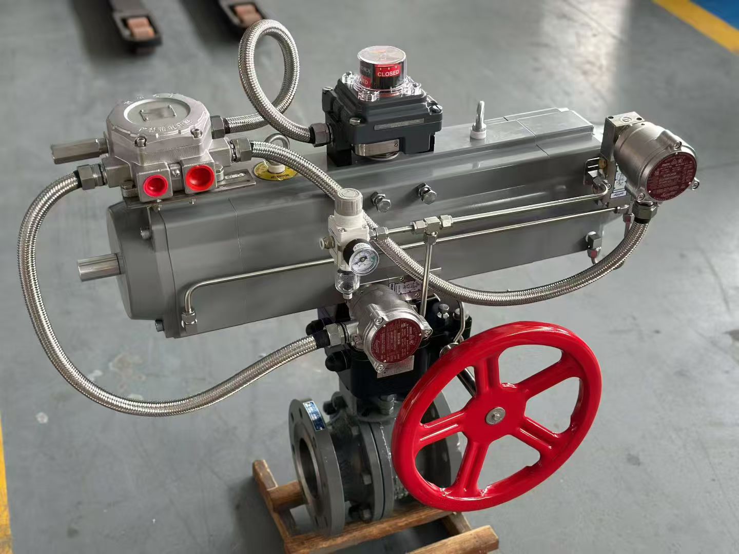 Figure 1: Typical pneumatic two-stage ball valve assembly — three-stage actuator with limit switches, solenoid valves and manual emergency handwheel
How Three-Stage Pneumatic Actuators Work
The three-stage pneumatic actuator is the core power unit that enables two-stage control. Its structural features include:
- Dual-chamber segmented design: The actuator contains two independent pneumatic chambers (A and B). Chamber A controls the first-stage stroke (typically 0°→45° or 0°→50°), and chamber B controls the second-stage stroke (45°→90°). Each chamber is supplied by an independent solenoid valve, with PLC or relay-based sequential interlocking.
- Intermediate limit mechanism: A mechanical limit device inside the actuator ensures automatic stop after the first-stage stroke, awaiting the second-stage command. This limit can be adjusted via screws to suit different valve sizes and process requirements.
- Spring-return and double-acting options: Two-stage valves can be configured with either double-acting actuators (requiring air for both open and close) or single-acting spring-return (automatic close on air failure), meeting different safety integrity requirements.
- Auxiliary control components: As shown in the photos, a typical three-stage actuator is fitted with solenoid valves, filter-regulator-lubricators (FRL), limit switches, and a manual emergency handwheel. Limit switches provide real-time valve position feedback, ensuring the control system accurately knows the "small opening" and "full open" positions.
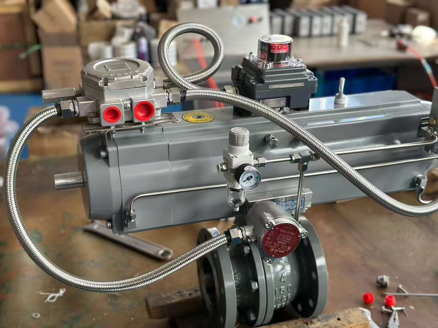 Figure 2: Workshop assembly details — visible solenoid valve manifold, limit switch boxes and stainless steel braided air supply lines
Typical Tank Filling Two-Stage Valve Applications
The tank filling two-stage valve is the most typical application of pneumatic two-stage ball valves in the field of storage tank loading. Its core advantage is preventing static electricity, impact, and foam generation during the initial high-speed filling phase, while ensuring efficiency during the high-flow phase.
Typical Process Sequence
- Pre-opening stage (first stage): When loading begins, actuator chamber A operates, opening the valve to a small angle of 30°~50°. The medium enters the tank at a low flow rate, avoiding static electricity buildup and splashing.
- Full-opening stage (second stage): When the liquid level reaches a safe height or after a preset delay, the control system triggers chamber B, and the valve continues to open to 90° fully open, entering the high-flow rapid filling stage to shorten the overall loading time.
- Two-stage closing (optional): For high-precision filling, a two-stage closing logic can also be used — first quickly closing to a small opening for a "trickle finish," then fully closing to prevent dripping and impact.
Applicable Industries
- Petrochemical storage and transportation: Loading and unloading of crude oil, refined oil, and chemical solvents into tank trucks and storage tanks
- Food and pharmaceutical: Impact-free filling of edible oils, syrups, and medicinal liquids
- Water treatment: Controlled water intake for large tanks and reaction vessels
- LNG / cryogenic media: Two-stage safety control for cryogenic liquid loading arms
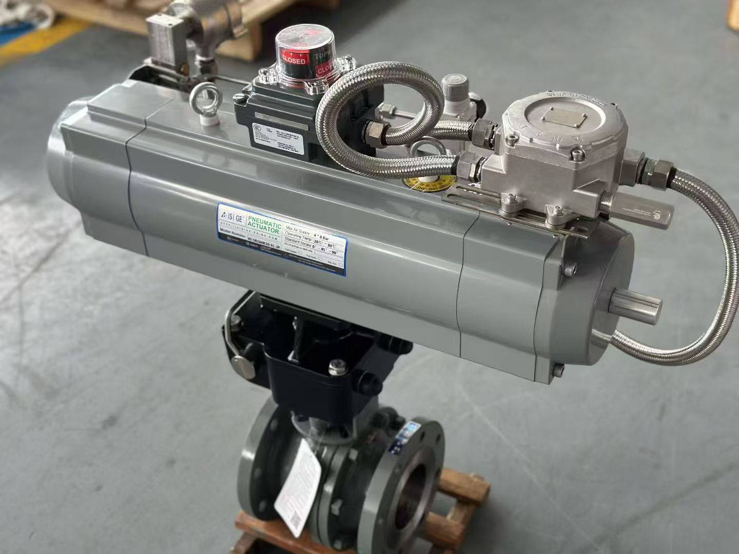 Figure 3: Side view of three-stage actuator — actuator label, air connections and valve body mounting details
Selection Criteria and Technical Parameters
When selecting a pneumatic two-stage ball valve, the following technical parameters and operating conditions should be carefully considered:
- Segmented angle setting: The first-stage stroke angle (usually 30°~50°) must be matched to the process flow rate. Too small an angle causes excessive throttling; too large defeats the purpose of impact prevention. It is recommended to calculate based on medium flow rate, tank diameter, and loading volume.
- Actuator torque: The total output torque of the two-stage actuator must exceed the operating torque of the ball valve under maximum pressure differential, with a safety factor of 1.3~1.5. Note: the pressure differential across the ball valve is greatest at small opening angles during the first stage, and torque demand is also highest at this point.
- Response time and sequence control: The delay between the two stage actions (usually 1~10 seconds) is set by the solenoid valves and control system. Ensure that the PLC or relay logic is reliable to prevent damage from simultaneous activation of both stages.
- Sealing and materials: Select valve body material (WCB, CF8, CF8M, etc.) and sealing material (PTFE, RPTFE, metal seal, etc.) based on medium corrosiveness. For petrochemical media, soft-sealed ball valves with fire-safe and anti-static design are recommended.
- Safety interlocking: It is recommended to configure limit switches (mechanical or inductive) to feed back the two-stage position signals to the DCS / PLC, implementing a hard interlock of "do not proceed to the next stage until position is reached."
- Manual emergency: As shown in the assembly photos, the actuator should be equipped with a manual emergency handwheel (the red handwheel in the photos) to allow manual valve operation in the event of air or power failure.
Advantages Over Conventional Pneumatic Ball Valves
| Comparison Item | Conventional Pneumatic Ball Valve (Two-Position) | Pneumatic Two-Stage Ball Valve (Three-Stage Actuator) |
|---|---|---|
| Opening method | 0° → 90° direct full open | 0° → 45° (first stage) → 90° (second stage) |
| Flow control | No adjustment, high initial impact | Small flow pre-fill, then high flow loading |
| Static / impact | High-speed media prone to static buildup | First-stage low speed suppresses static and splashing |
| Actuator structure | Single-chamber double-acting or spring-return | Dual-chamber three-stage with intermediate limit |
| Control complexity | Simple (single solenoid valve) | Requires dual solenoid valves + sequence / interlock control |
| Applicable scenarios | General on/off control | Tank filling, dispensing, quantitative loading/unloading |
Installation and Maintenance Recommendations
- Air supply requirements: The supply pressure should be stable (recommended 0.4~0.6 MPa), with a filter-regulator-lubricator (FRL) and lubricator installed to prevent impurities from entering the actuator chambers and causing segmented action failure.
- Piping layout: The piping from solenoid valves to the actuator should be as short and equal-length as possible, to avoid inconsistent response times between the two stages. Stainless steel braided hoses (as shown in the assembly photos) are recommended for flexibility and pressure resistance.
- Periodic calibration: Every 3~6 months, check whether the intermediate limit screws have shifted, test the two-stage action sequence for normal operation, and ensure limit switch signals are accurate.
- Winter protection: In cold regions, the air supply system should be equipped with a dryer and heater to prevent condensation from freezing and causing actuator jamming.
Conclusion
Through the ingenious design of the three-stage pneumatic actuator, the pneumatic two-stage ball valve upgrades a traditional "on/off" ball valve into a precision flow control device capable of segmented flow regulation. In applications such as tank filling, chemical loading, and food dispensing, the tank filling two-stage valve effectively suppresses static electricity, reduces impact, and minimizes foam, balancing safety and efficiency. During selection, focus on the segmented angle, actuator torque, sequence control logic, and safety interlock configuration to ensure precise and reliable two-stage operation, providing a safer and smarter solution for industrial fluid control.
什么是气动两段球阀
气动两段球阀(又称气动两段阀、装罐两段阀)是一种通过三段式气动执行器实现分段开启或关闭的球阀控制方案。与传统气动球阀的"全关-全开"两位式控制不同,两段球阀能够在 0°→45°→90°(或反向)两个阶段中精准控制流量,广泛应用于储罐装料、化工装卸、液体灌装等对流量控制要求严格的场景。
其核心组件是一套三段式气动执行器——该执行器内部配备两套独立的活塞腔室,通过外部电磁阀的时序控制,实现"第一段快速小开度→第二段全开"或"第一段快速小关度→第二段全关"的两段式动作曲线。
图1:气动两段球阀典型装配——三段式气动执行器搭配限位开关、电磁阀及手动应急手轮三段式气动执行器的工作原理
三段式气动执行器(Three-Stage Pneumatic Actuator)是实现两段控制的核心动力单元。其结构特点如下:
- 双腔分段设计:执行器内部包含 A、B 两个独立的气动腔室。腔室 A 控制第一段行程(通常为 0°→45° 或 0°→50°),腔室 B 控制第二段行程(45°→90°)。两个腔室分别由独立的电磁阀供气,通过 PLC 或继电器实现时序联锁。
- 中间限位机构:执行器内部设有机械限位装置,确保第一段行程结束后自动停止,等待第二段指令。该限位可通过调节螺钉设定,适应不同口径和工艺要求。
- 弹簧复位与双作用可选:两段阀既可配置双作用执行器(需气源开/关),也可配置单作用弹簧复位(失气自动关闭),满足不同安全等级需求。
- 辅助控制组件:如上图所示,典型的三段式执行器外配电磁阀、过滤减压阀、限位开关(Limit Switch)和手动应急手轮。限位开关实时反馈阀位状态,确保控制系统精确掌握"小开度"和"全开"两个位置。
图2:三段式气动执行器车间装配细节——可见电磁阀、限位开关盒及不锈钢编织供气管路装罐两段阀的典型应用场景
装罐两段阀(Tank Filling Two-Stage Valve)是气动两段球阀在储罐装料领域中最典型的应用。其核心优势在于:防止高速灌装初期产生静电、冲击和泡沫,同时在大流量阶段保证效率。
典型工艺流程
- 预开阶段(第一段):装料开始时,执行器腔室 A 动作,阀门开启至 30°~50° 小开度。此时介质以较低流速进入储罐,避免静电积聚和喷溅。
- 全开阶段(第二段):当液位达到安全高度或经过延时后,控制系统触发腔室 B,阀门继续开启至 90° 全开,进入大流量快速灌装阶段,缩短整体装料时间。
- 两段关闭(可选):对于高精度灌装,也可采用两段关闭逻辑——先快速关至小开度进行"细流收尾",再完全关闭,防止滴漏和冲击。
适用行业
- 石化储运:原油、成品油、化工溶剂的罐车/储罐装卸
- 食品医药:食用油、糖浆、药液的无冲击灌装
- 水处理:大型水池、反应釜的受控进水
- LNG / 低温介质:低温液体装车臂的两段式安全控制
图3:三段式气动执行器侧面——执行器本体标签、气源接口及阀体连接细节选型要点与技术参数
在选型气动两段球阀时,需重点考虑以下技术参数和工况条件:
- 分段角度设定:第一段行程角度(通常 30°~50°)需与工艺流速匹配。角度过小则节流过度,过大则失去防冲击意义。建议根据介质流速、储罐直径和装料量计算。
- 执行器扭矩:两段执行器的总输出扭矩必须大于球阀在最大压差下的操作扭矩,并考虑 1.3~1.5 安全系数。注意:第一段小开度时球阀前后压差最大,扭矩需求也最高。
- 响应时间与时序控制:两段动作之间的延时(通常 1~10 秒)由电磁阀和控制系统设定。需确保 PLC 或继电器逻辑可靠,防止两段同时动作导致执行器损坏。
- 密封与材质:根据介质腐蚀性选择阀体材质(WCB、CF8、CF8M 等)和密封材质(PTFE、RPTFE、金属密封等)。对于石化介质,建议选用防火防静电设计的软密封球阀。
- 安全联锁:建议配置限位开关(机械或感应式)将两段位置信号反馈至 DCS / PLC,实现"未到位不进入下一段"的硬联锁保护。
- 手动应急:如装配图所示,执行器应配备手动应急手轮(图中红色手轮),确保在失气或断电状态下可人工操作阀门。
与普通气动球阀的对比优势
| 对比项 | 普通气动球阀(两位式) | 气动两段球阀(三段式执行器) |
|---|---|---|
| 开启方式 | 0° → 90° 直接全开 | 0° → 45°(第一段)→ 90°(第二段) |
| 流速控制 | 无法调节,初始冲击大 | 先小流量预热,再大流量灌装 |
| 静电/冲击 | 高速介质易产生静电积聚 | 第一段低速抑制静电和喷溅 |
| 执行器结构 | 单腔双作用或单作用 | 双腔三段式,带中间限位 |
| 控制复杂度 | 简单(单电磁阀) | 需双电磁阀 + 时序/联锁控制 |
| 适用场景 | 一般开关控制 | 储罐装料、灌装、定量装卸 |
安装与维护建议
- 气源要求:供气压力应稳定(建议 0.4~0.6 MPa),并配置过滤减压阀(FRL)和油雾器,防止杂质进入执行器腔室导致分段动作失效。
- 管路布置:电磁阀至执行器的管路应尽量短且等长,避免两段响应时间不一致。建议使用不锈钢编织软管(如图中装配),兼顾柔韧性与耐压性。
- 定期校验:每 3~6 个月检查中间限位螺钉位置是否偏移,测试两段动作时序是否正常,确保限位开关信号准确。
- 冬季防护:在寒冷地区,气源系统需配置干燥器和加热器,防止冷凝水结冰导致执行器卡滞。
总结
气动两段球阀通过三段式气动执行器的巧妙设计,将传统"开关式"球阀升级为具备流量分段控制能力的精细调节设备。在储罐装料、化工装卸、食品灌装等场景中,装罐两段阀能够有效抑制静电、降低冲击、减少泡沫,兼顾安全与效率。选型时应重点关注分段角度、执行器扭矩、时序控制逻辑及安全联锁配置,确保两段动作精确可靠,为工业流体控制提供更安全、更智能的解决方案。